1564
Rapid 3D MR Fingerprinting reconstruction using a GPU-based framework1Radiology, Case Western Reserve University, Cleveland, OH, United States, 2Biomedical Engineering, Case Western Reserve University, Cleveland, OH, United States, 3Siemens Medical Solutions, Boston, MA, United States, 4Health Futures, Microsoft Research, Seattle, WA, United States
Synopsis
In this study, we proposed an efficient online map reconstruction framework for 3D MRF using a GPU-based reconstruction. Both SVD compression and 2D NUFFT were performed mostly during data acquisition and GPU computation was further implemented to accelerate coil combination and pattern matching. Our simulation results demonstrated that 1) accurate T1 and T2 mapping was obtained with the proposed method and 2) rapid MRF tissue mapping can be achieved in ~ 0.7 sec per slice, which enables rapid volumetric quantitative imaging using MRF.
Introduction
MR Fingerprinting (MRF) is a quantitative imaging framework which can provide simultaneous quantification of multiple tissue properties (1). Unlike conventional approaches, MRF uses a variable acquisition to generate incoherent signal time courses and retrieves quantitative tissue properties using a pattern matching algorithm. While this technique has demonstrated rapid acquisition speed, the quantitative map reconstruction using non-uniform FFT (NUFFT) and pattern matching can be complex and relatively slow. This creates special challenges for volumetric MRF acquisitions, hindering its clinical applications. Singular value decomposition (SVD)-based approaches have been previously proposed to accelerate 2D MRF reconstruction (2). A Gadgetron-based framework has also been developed to facilitate online MRF reconstruction (3). Based on these prior studies, we proposed an efficient online map reconstruction framework for 3D MRF and demonstrated that rapid reconstruction can be achieved with the aid of GPU computation in this framework.Methods
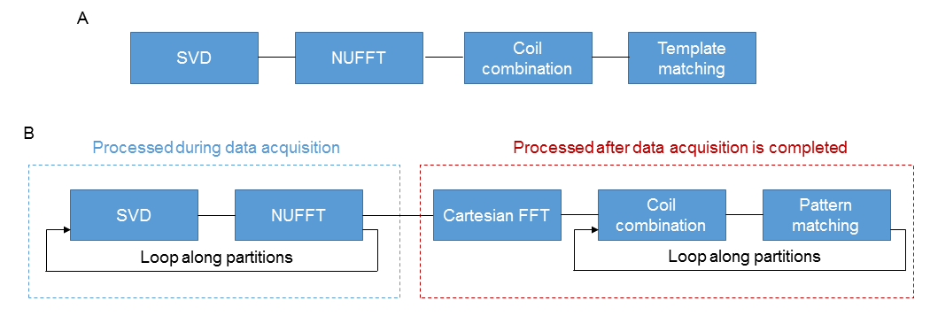
As a proof of concept, a 3D MRF dataset from an agarose phantom was acquired on a Siemens 3T scanner (MAGNETOM Skyra, Siemens Healthcare, Erlangen, Germany) using a 20-channel multi-array receiver head coil. A prototype 3D MRF sequence using variable flip angles and golden-angle spiral trajectories was used (4, 5). A total of 768 time frames were acquired for each partition and the 3D MRF acquisition was repeated sequentially across all the partitions. The acquisition time for each partition was 14 sec with a 2-sec waiting time at the end of acquisition of each partition. Other imaging parameters included: FOV, 30×30 cm; matrix size, 256×256; slice thickness, 3 mm; number of slices, 8; flip angles, 5°~12°; number of receive channels, 8. The total acquisition time for the 3D acquisition was about 2 min. The acquired MRF dataset was converted to the ISMRMRD format for following online reconstruction.The map reconstruction was performed on a standalone workstation (10 core, 2.2GHz Intel Xeon E5-2630 v4 processor; and 64GB RAM) with an 8GB Nvidia GeForce GTX 1080 graphics card. Built upon a prior 2D MRF reconstruction pipeline using Gadgetron (Fig. 1a), an efficient reconstruction framework for 3D MRF was developed (Fig. 1b). Briefly, after the data acquisition for each partition was completed, a SVD-based compression was performed to compress the data from 768 timepoints to only 17 singular vector volumes. A GPU-enabled 2D NUFFT was then applied to grid the data. These two steps can be performed during the acquisition of the next partition to save map reconstruction time. After all partitions were acquired, a Cartesian FFT was performed along the partition direction, followed by coil combination and pattern matching. To further accelerate the data processing, a GPU-based coil combination (6) and pattern matching were implemented to replace previous methods using CPU. We validated the quantitative accuracy of the proposed reconstruction framework on the acquired phantom dataset and the results were compared to those obtained using 1) MATLAB and 2) Gadgetron with coil combination and pattern matching implemented on CPU (Gadgetron-CPU).
Results
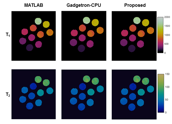
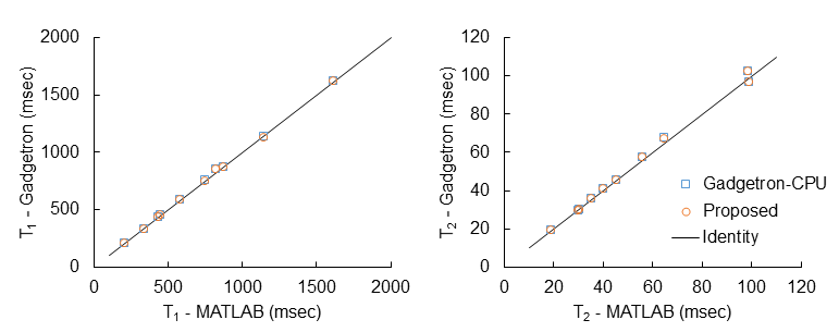
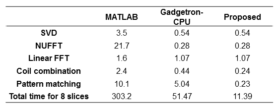
Fig. 2 shows the quantitative T1 and T2 maps obtained from the agarose phantom using three different map reconstruction frameworks. The extracted T1 and T2 values are plotted in Fig. 3. These results demonstrated a good agreement in both T1 and T2 values among the proposed method.Tab. 1 lists the post-processing times for the individual steps of all three methods. The total reconstruction time with the proposed framework was 11 sec, while it was 303 and 51 sec for MATLAB and Gadgetron-CPU reconstruction, respectively. More importantly, 5.6 out of 11 sec can be finished during the data acquisition window and the effective processing time after the data acquisition was completed was approximately 0.7 sec per slice.
Discussion and Conclusion
In this study, an efficient GPU-based 3D MRF reconstruction was proposed. While the method was only examined on a phantom dataset due to the COVID pandemic, our results suggest that rapid post-processing with a volumetric coverage is feasible. For example, with a whole brain coverage (60 slices), the waiting time for all quantitative T1 and T2 maps to be presented on the host monitor is about 40 sec, which is acceptable for the routine clinical workflow. The proposed framework is also highly parallelizable and the processing time can be further reduced when multiple GPU cards are available. Coupled with the rapid acquisition speed, the proposed reconstruction framework will allow rapid MRF map reconstruction to enable large-scale clinical studies using this novel quantitative imaging technique. Future studies will be performed to implement this method for in vivo quantitative assessment.Acknowledgements
No acknowledgement found.References
1. Ma D, et al. Nature, 2013; 187–192.
2. McGivney DF, et al. TMI, 2014; 2311-2322.
3. Lo W, et al. ISMRM workshop on Magnetic Resonance Fingerprinting, 2017.
4. Chen Y, et al. Radiology, 2019; 33-40.
5. Chen Y, et al. NeuroImage, 2020; 116329.
6. Walsh DO, et al. MRM, 2000; 682-690.
Figures